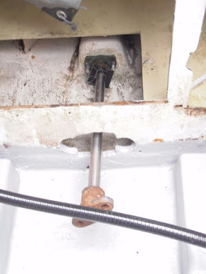
Backing pad held in place
This morning I removed the bolts and put the hole saw through to open up the hole in the pad working from both sides to reduce the risk of splintering as the hole saw broke through.
Hole cut out
Just need to give them a coat of epoxy then I can fit the sea cocks decided to go with Marelon plastic its a carbon reinforced nylon.
After a bit of searching around Ifound some flexible engine mounts that will fit I calculated that there was 40mm between the engine feet and the bearers I found that the mounts that Parts 4 Engines sell for the Perkins 4-108 are only 38.5mm high without the height adjusting stud so a quick e-mail to the firm to confirm that they can be installed by bolting them directly to the engine feet and then any height adjustment can be carried out with shims under the mount. Tony Robins at Parts 4 Engines is very helpful and prompt with replies to queries. The next problem is the original mounts had bolts on 5.5" centres and the new ones are on 4" centres the plan is to recess some 50mm x 10mm steel into the top face of the engine bearers and then drill and tap at 4" centres and bolt the new mounts down with 10mm set bolts.
Original position of engine mount
The two aft mounts are secured by coach screws directly into the timber engine bearers this method will be reused to secure the steel plates the forward mounts are secured with nuts and bolts as there is sufficient depth in the bearer to allow a slot through the bearer so as to be able to fit nuts and bolts.
Recess cut out for mounting plate
Mounting plate in place
The mounting plates will be drilled and tapped once the engine has been put in place and lined up


