Sunday 30 October 2016

Windows

I have now got the saloon windows stripped and resealed the port side one was refitted last Monday.

Last week was a short week as I had a days sailing with a friend on Friday moving his new boat from Medway Yacht Club round to Conyer. It was a pleasant days sailing, warm for the time of year, albeit an early start, up at 04.00 over to Conyer to leave my car there and then on to Lower Upnor to pick up the boat. We got away just after 07.00 and arrived in Conyer just on the high water at midday. There was not a lot of wind about so it was a case of motor sailing all the way in order to arrive in time to get up the creek to Swale Marina.

Anyway back to windows I went over to Queenborough yesterday morning and removed the starboard saloon window and stripped it and cleaned out all the old mastic from the flange photograph shows port side window starboard side was similar.


Saloon window with old mastic and bedding tape removed

The screws holding the two parts of the frame together were then removed and the two parts were gently prised apart using a sharp wood chisel by inserting it into the joint and gently twisting once the bond had broken it was just a matter of carefully pulling the two halves apart.


Screws holding the frame together

Once the frames had been split and the glazing removed, these are toughened glass unlike the fore and aft cabin windows, it was just a matter of removing the old mastic seals. I cleaned everything up with white spirit and then followed up with a good wash with hot water and detergent, Once everything had been thoroughly dried I put a good fillet of Arbosil 1098 into the channel of the lower half of the frame.


Lower half of frame with Arbosil 1098 fillet

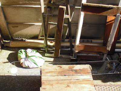
To hold the glass central in the channel I used some short pieces of rubber channel, approximately 1/4" long, which were put over the glass before it was pressed into position in the channel. The workbench is an old wooden box and the gap between the boards is just right for holding the frame upright.


Short pieces of rubber channel attached to the glass


Glass pressed into position

Once the glass was in place I added some more pieces of rubber channel to the top half of the glass before putting a fillet of Arbosil 1098 into the channel on the top half of the frame and then pressing it into place. Once the top half of the frame was in position I replaced the fixing screws. This was followed up by an inspection to make sure that the mastic was evenly squeezed out on both sides of the channel where this had not happened it was just a matter of running the mastic gun along those areas and squeezing some more into the channel I then did a quick preliminary clean up by running a sharp wood chisel around the frame to remove the majority of the mastic that had been squeezed out. After lunch I gave the frames a wipe round with white spirit to remove any mastic, once that had been done I left the window to allow the mastic to cure.
Cleaning up with a wood chisel works fine for glass but on the other windows which have acrylic glazing I used a soft plastic scraper and then white spirit and a rag to clean them up.


Starboard window completed

The starboard window will be refitted tomorrow all that will be required will be some rain to test them that only leaves the fore hatch the acrylic glazing is OK but it is coming away from the frame which will require it to be removed and resecured using an extremely sticky double sided tape that will be the next homework job.




Friday 21 October 2016

Bit of a milestone

I reached a bit of a milestone this week, and in theory the boat should now float as I have filled all the holes below the waterline. I started the week by sanding the new GRP on the skeg repairs and redundant hull openings and then adding an epoxy fairing compound, a mixture of epoxy and West 407 lightweight fairing filler, which was then left to cure.


Fairing compound applied

Once the fairing compound had cured I sanded it down, the sanding was done free hand but I used a flexible batten laid around the curve of the hull to check the profile.


Fairing compound after sanding

After sanding there were a couple of small areas that needed a further application of the fairing compound where the heads seacock and log openings had been made good.

Finally the last holes below the water line were filled when I fitted the new hull anode there is still some work to be done below the waterline before she can go back in the water, the rust needs to be removed from the keel so that the bottom can be anti fouled and the propeller still needs to be fitted.


New hull anode

To finish up with GRP work for the time being I dealt with a couple of persistent rainwater leaks the hull to deck joint. On the Moody 33 the deck is joined to the hull with pop rivets the join is subsequently glassed over but in a couple of places around the bolts that retain the toe rail there were a couple of annoying leaks. I had tried putting penny washers and Sikaflex sealant under the nuts to no avail and in further investigation found a couple of areas where the glass fibre mat had not been properly wetted out allowing water to leak through. I cut back to sound GRP with a sharp wood chisel and then made good with some glass mat and epoxy resin.

Finally to finish up today I removed the port side saloon window for refurbishment there had been a leak I think between the frame and the coach roof side but while it is out I will reseal the glass into the frame at some time it has been patched up with silicone sealant this will be this weekends homework project. Once the port window has been replaced I will refurbish the starboard one, it doesn't leak at the moment but the seal between the glass and frame is hard and showing some signs of cracking. It is inevitable that once the boat is back in the water and sailing there will be some flexing of the hull which will cause the window to leak.


Friday 14 October 2016

GRP Repairs

Last Friday 7th October I borrowed a generator and set to work to grind out the GRP around the cracked areas of the skeg and the redundant openings in the hull. The area around the two hull openings, original heads discharge valve and the old paddle wheel log, were ground back at 1 in 12 to provide a good base for the new GRP. I cut out a simple gauge from ply to check on the angle. Unfortunately I did not take any photographs of this operation as I had left the camera at home. The grinding was carried out with a 41/2" angle grinder that I purchased from Screwfix some time ago it is a variable speed model which I find useful for GRP work as it gives a bit more control of the rate of removal of material. The original plan was to grind back on a taper on the inside as well as the outside of the hull but unfortunately I had a problem getting access to the inside of the hull with the angle grinder so I decided to lay up the GRP on the outside first. I fitted a polythene covered piece of ply over the openings from the inside with a timber wedged against the underside of the deck to hold them in place. I followed the usual procedure for this type of work by cutting out a piece of glass cloth to suit the outer extremity of the prepared area and then cut more of the same shape but gradually reducing in size. I then cleaned up both sides with acetone and gave them a good sanding to provide a key for the new material. Once the outside GRP had been laid up I waited for it to begin to gel before removing the blanks and laying up the GRP on the inside making sure that I had a good bond between the inner and outer layers in the opening and left it to cure. Meanwhile I got on with laying up the new GRP to the defective areas of the skeg again by cutting a series of pieces of glass cloth each reducing in size and laying them in largest first. I would recommend the West Epoxy handbook it is a most useful publication when it comes to this type of work. While working with epoxy I cleaned up the damaged area above the rudder on the starboard side, it looks as though something had become jammed between the hull and the rudder, but it had caused the gel coat to break away  along the edge. This area was repaired using epoxy thickened, to a peanut butter, West Epoxy handbook wording not mine, consistency, with colloidal silica.


Repairs to starboard side of skeg


Repairs to port side of skeg


Infill to redundant heads discharge opening


Infill to redundant log opening


Log opening internal


Heads discharge opening internal

There is a bit of a depression in the GRP on the inside of the log opening this is because the hull is much thicker in this area and to grind out too full depth would entail the work crossing over the centre line to the port side which I was not keen on doing so I worked the layers of glass cloth well in to give a good bond to the outside work.

I have used a number of brushes for this work fortunately there is a Poudland just up the road which is selling everything at 90p you get five brushes endorsed by Tommy Walsh, remember he of Ground Force, they don't like acetone or white spirit much makes the bristles fall out but at that price for GRP work they can't be beaten.

I also found time to fit the new heads discharge seacock so once the hull anode has been fitted  the boat will be watertight from the sea water side there will still be a bit more to do before she can go in though. Next week the plan is to fill and fair the repaired areas where necessary. 


Heads discharge seacock fitted

Work is progressing at a reasonable rate but these jobs always take a lot longer than originally planned fortunately up to now there has been very little in the way of nasty surprises although there is still a way to go yet.


Saturday 8 October 2016

Wind instruments

Among the fairly ancient electronics that came with New Morning was a set of Walker wind instruments one of the anemometer cups was damaged there was evidence of it having been repaired and then broken again. It was made of a flexible plastic somewhat akin to polythene which does not generally take very well to glue also the ball race anemometer bearings were worn out. The dials looked OK and the wind vane moved freely without any slack in the bearings and it was obviously a good solid piece of kit, but up to now that is as far as I had got with the system until this last week. The first job was to try and source some new anemometer cups the company that deals with Walker wind instruments could not help but they did offer me a replacement system for about £1500 or a budget system for £1060. Now I have never owned a boat with a set of wind instruments I have found a simple windex quite sufficient however as I had the system I thought I might as well add it to the challenge of rebuilding New Morning.

The first job was to strip and examine the anemometer head this was quite straightforward and it came apart quite easily.


Anemometer stripped

The bearings have a shoulder on the outer race and I thought that they may might have been a problem but I found some on a site called Simply Bearings ordered on Monday afternoon delivered by post Tuesday. The cups were going to be a bit more of a problem. Being an engineer my first thought was to make some new ones, not a difficult task, I decided that they would in all probability be too heavy to give a reasonably accurate indication of wind speed especially, in light airs as I would have probably used a combination of brass and copper, aluminium would possibly have been OK but the difficulty would have been in joining it together. I considered 3D printing however on consulting a higher authority, namely number two daughter who knows about these things, we decided that the shape and the available material would not be compatible there are some very thin sections. Finally I looked at other manufacturers equipment the problem was that they don't give a drawing showing the dimensions  however I came across spares for a VDO anemometer on the Furneaux Riddall website that did give the size of the cups and by a bit of scaling of the photograph it turned out that the PCD of the cups was a bit less than that of the Walker unit but the cups were a bit larger and the boss would need to be adapted to fit so I ordered one I figured that it was worth a try at £8.


The VDO and Walker cups

The VDO cups fit on a fairly thin spindle while the Walker spindle is of a much larger diameter with a hexagonal section to give a positive drive although this is probably a bit of overkill. I opened out the bore of the boss of the VDO cups and then machined the boss of the original cups down so that the new cups were a good fit.


Opening out the bore of the VDO cups


Machining the boss of the Walker cups


Machining completed


Parts assembled

The new bearings were assembled into the housing with loctite as they were sliding fit and then the spindle was replaced and secured with a 'C' clip the second part with the hexagonal section is secured by means of a small roll pin.


Bearings in place


Spindle in place

The anemometer operates on a pulse system or at least I assume that is how it works there is a rotor with 4 lobes that passes through what I take to be a magnetic field.


Rotor showing 4 lobes


Lobes pass through the gap

The body of the anemometer was then fitted back onto the masthead unit with the six countersunk machine screws the anemometer cups were then fitted and secured with the original nut to complete the job.


Complete masthead unit

At the moment I am not sure about the possible accuracy of the wind speed indicator the anemometer cups are larger than the original but the PCD is smaller whether or not they will cancel each other out I won't know until the mast is up  and the system wired up as the masthead unit fits into a multi pin socket on the mast I have no way of rigging a temporary connection. The other deviation from the original is that the new cups revolve in the opposite direction to the old ones I had to turn them over to fit them but as this is a pulse system it should make no difference.

I have connected a 12 volt supply to the dials and the two wind direction indicators do move and the back lighting works so there is every possibility that the system will work once the mast is up I shall be able to check the operation before deciding where to install the dials.


Dials