However back to work I ordered a new 45 degree cast aluminium exhaust elbow from Parts 4 Engines and while I was waiting for it to arrive I carried on with painting the area for the engine panel mount and then started looking at the mounting position for the electrical panel as originally it had been mounted where I had decided to mount the engine panel. Looking at photographs of Moody 33s for sale it would appear that most seem to have it behind the companionway steps so that is where I decided to put it along with the battery selector switch. The original selector switch is a conventional 1,2,both or off type it looks as though it was part of the original fit out I have opened it up for a look see and decided that it is fit for further service.
Position of electrical panel
I was going to paint the area before building the panel mount but as the previous owner had started lining the transverse bulkheads with an off white laminate and as the area was pretty rough also some spare laminate came with the boat I decided to follow suite so cut and fitted the first panel. The electrical panel will be mounted in a box built in the space above this laminate panel the battery selector switch will be mounted a little bit higher than shown in the photograph at the moment its only resting on the top of the battery locker.
Laminate panel in place with battery selector switch
The exhaust elbow duly arrived on Wednesday after being ordered on Monday evening good service from Parts 4 Engines so today I got on with fitting it and getting the rest of the exhaust system sorted.
New exhaust elbow
Elbow in position
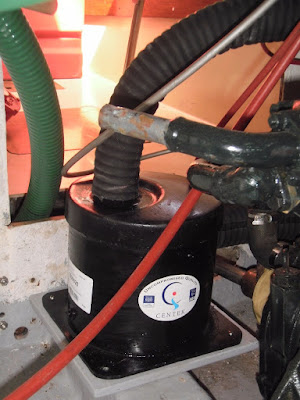
The first problem was that the exhaust elbow fouled the sea water pipe from the oil cooler to the the gearbox I can get round this by replacing the copper pipe with a flexible hose in the above photograph the pipe has already been removed. The second problem can just be seen in the above photograph the end of the elbow is very close to the inlet on the water lock the connecting hose would be very short and would need a very tight bend to connect the two this would be no problem had the engine been rigidly mounted but as the water lock is rigidly mounted and the engine on flexible mounts the short length of hose bent to a small radius would not give the required flexibility so back to the drawing board.
I spent some time moving the water lock around until I came up with a position that would give the required flexibility it meant moving the water lock and its mounting plate to the other side of the engine and turning it through 90 degrees as can be seen in the photograph below the revised position will also reduce the strain on the hose connections on the water lock all that is left to do is fit the hose clips then the exhaust system will be complete.
Revised water lock position


No comments:
Post a Comment