Friday, 29 July 2016

Engine panel

There is not a lot to show in the way of photographs for this week Monday saw the engine panel installed and wired I took the opportunity to tidy up the wiring to the engine hours meter and the ammeter. The battery selector switch is now installed with the positive battery cables and the positive cable to the engine connected the photograph below shows the excess length of the engine wiring harness coiled up I am always a bit reluctant to cut these down I don't know why as its not likely to ever be used on this boat.


Wiring harness ready to connect to panel


Engine panel in place

Wednesday and today has been spent cutting out and laminating plywood panels to make up the mounting arrangement for the electrical switch panel not really much to photograph just bits of ply. The mounting for the switch panel will also form a trunking to carry the engine wiring harness up to its panel it will also conceal as much of the other general wiring as possible together with the distribution bus bars and connectors etc.

I finished up by running the engine fuel line from the lift pump to the primary filter and then into the starboard cockpit locker to await the installation of the fuel tank. 

Friday, 22 July 2016

Exhaust and first thoughts on electrical panel

I got back from the Dartmouth trip on Sunday took us four days with no overnight sailing the wind was on the nose most of the way and because of the timetable we did a lot of motor sailing. On Saturday it may have been hot ashore believe me crossing Lyme Bay the wind was cold.

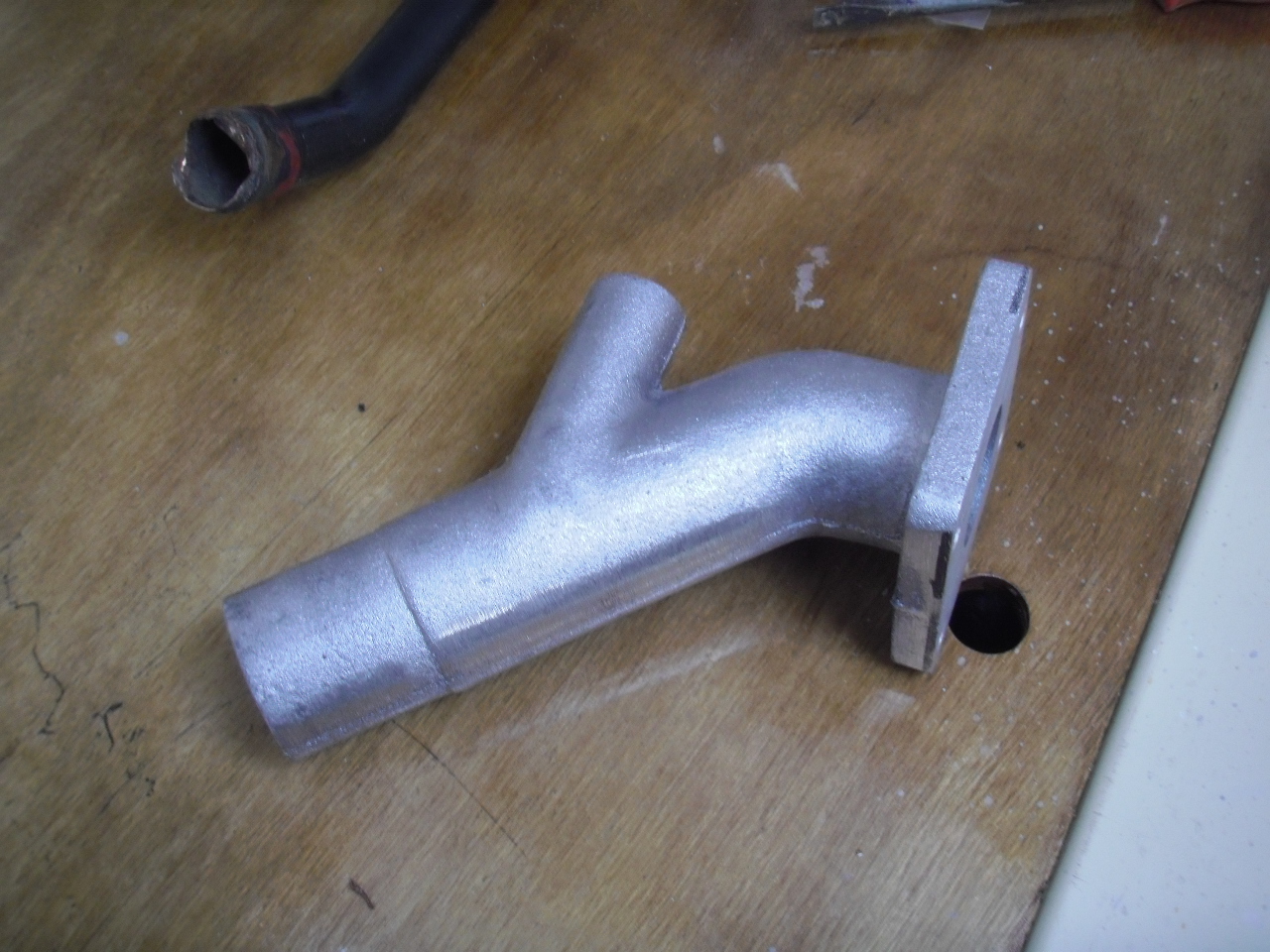
However back to work I ordered a new 45 degree cast aluminium exhaust elbow from Parts 4 Engines and while I was waiting for it to arrive I carried on with painting the area for the engine panel mount and then started looking at the mounting position for the electrical panel as originally it had been mounted where I had decided to mount the engine panel. Looking at photographs of Moody 33s for sale it would appear that most seem to have it behind the companionway steps so that is where I decided to put it along with the battery selector switch. The original selector switch is a conventional 1,2,both or off type it looks as though it was part of the original fit out I have opened it up for a look see and decided that it is fit for further service.


Position of electrical panel

I was going to paint the area before building the panel mount but as the previous owner had started lining the transverse bulkheads with an off white laminate and as the area was pretty rough also some spare laminate came with the boat I decided to follow suite so cut and fitted the first panel. The electrical panel will be mounted in a box built in the space above this laminate panel the battery selector switch will be mounted a little bit higher than shown in the photograph at the moment its only resting on the top of the battery locker.


Laminate panel in place with battery selector switch


The exhaust elbow duly arrived on Wednesday after being ordered on Monday evening good service from Parts 4 Engines so today I got on with fitting it and getting the rest of the exhaust system sorted.


New exhaust elbow


Elbow in position


The first problem was that the exhaust elbow fouled the sea water pipe from the oil cooler to the the gearbox I can get round this by replacing the copper pipe with a flexible hose in the above photograph the pipe has already been removed. The second problem can just be seen in the above photograph the end of the elbow is very close to the inlet on the water lock the connecting hose would be very short and would need a very tight bend to connect the two this would be no problem had the engine been rigidly mounted but as the water lock is rigidly mounted and the engine on flexible mounts the short length of hose bent to a small radius would not give the required flexibility so back to the drawing board.

I spent some time moving the water lock around until I came up with a position that would give the required flexibility it meant moving the water lock and its mounting plate to the other side of the engine and turning it through 90 degrees as can be seen in the photograph below the revised position will also reduce the strain on the hose connections on the water lock all that is left to do is fit the hose clips then the exhaust system will be complete.


Revised water lock position


Monday, 11 July 2016

More on the exhaust

I have made some progress since the last post but some time has been taken up with selling the Bowman 26 what with showing the purchaser round, taking him for a test sail and moving her round for lifting out for survey but she is now sold, the new owner took her away from Conyer on Saturday I am now back to owning just the one boat which is a much more sensible state of affairs.

I have managed to get some work done to the floors for the fuel tank these are now finished and painted ready for the ply to go down, once the ply is down and I have something to stand on I will paint the rest of the locker. The hoses in the photograph are for the engine space bilge pump discharge and the smaller one is the starboard cockpit drain the red cable is the steering cable.


Floors for fuel tank support


I ordered the water lock for the engine exhaust on Thursday from ASAP supplies and it arrived on Friday and that wasn't even supposed to be their next day delivery I have gone for a GRP Centek Vernalift as the space at the after end of the engine is a bit cramped and its lower than the Vetus with equivalent water capacity and being GRP it can withstand a higher temperature should the cooling water flow fail for any reason the Centek was about a fiver cheaper than the Vetus so not much in it price wise. I had already cut out a ply mounting plate for the water lock which I screwed directly to the engine bearers after giving the under side three coats of paint just need to put a couple more coats of paint on the top face before bolting the water lock down.


Water lock


Mounting plate for water lock


Water lock in position


Once I had the water lock in position I could finalise the route of the exhaust hose I decided to route it through the forward bulkhead in the aft cabin so I used a hole saw to cut a hole through the bulkhead the original opening can be seen below that will need making good not quite sure what I will do with it yet.


Exhaust hose re-routed


I have done a couple of small jobs in the engine space fitted the primary fuel filter and fitted a valve to the calorifier connection on the engine I found a couple of half inch Crane ball valves that came with the boat and was looking for a use for them, once the fuel tank has been installed the engine will be ready for a test run so I will be able to fill the cooling system without having to connect the calorifier which can be done later I still have one to fit on top of the engine.


Primary fuel filter in place


Calorifier isolation valve


I have also started work on the internal woodwork for the engine panel mount the panel was I believe mounted in the big hole in forward cockpit bulkhead but I would rather have it inside and now that I have made good that hole it won't fit anyway. The original Moody brochure shows it alongside the companionway which is where I have decided to put it I will have to find somewhere else for the electrical panel which was there, I have some thoughts on that. Most of the internal ply panels are covered with some form of imitation wood laminate which is not in particularly good condition the previous owner had already been using some white laminate on the bulkheads so I decided to do the same with the engine panel mount. This imitation wood is probably not one of the best features of the boat so the idea is to replace it with white laminate panels and reuse the original varnished hardwood trim. I have seen a few examples of this and it looks OK.


Trial fitting for the engine panel mount


That will be about all for this week as I am off on a sailing trip to Dartmouth weather permitting hoping to be back on Sunday.




Monday, 27 June 2016

Fuel tank and exhaust

I started on the installation of the fuel tank today the original tank was mild steel with a capacity of 45 gallons fortunately the previous owner had removed and disposed of this and provided a 25 gallon plastic tank. 45 gallons of diesel would probably last me a couple of seasons and with modern bio diesel apparently having an affinity for water and thus an increased risk of diesel bug the smaller tank would giving an increased turnover of fuel which would be a much better proposition.


Replacement fuel tank


Some time ago when working in the cockpit locker I had stood on one of the floors that support the tank and it broke away from the tabbing it was well soaked in diesel  so I decided that I would cut out a new one as in all probability epoxy would not adhere very well to the original fuel soaked ply. The tabbing looks a bit short but as this was the same length as the original I decided to keep it that good enough for Moody who am I to argue.


The new floor in place


The plan is to have a ply platform the length of the locker to provide even support to the new plastic tank and then strap it down using a securing kit from Tek Tanks.

Last week I measured for the new rubber exhaust hose and ordered 5 metres of 51mm hose from a company called Hyphose their prices reasonable if indeed anything for a boat can be considered reasonably priced these days. I ordered the hose on Wednesday evening and it arrived  on Friday. I have decided to dispense with the original cast iron water lock which I believe was mounted in the aft cabin with a length of flexible stainless steel pipe connecting it to the exhaust manifold. There are two reasons I am not keen on a hot exhaust pipe from the engine space through to the aft cabin also any deterioration could possibly cause exhaust gases to leak into the aft cabin with the attendant carbon monoxide risk it may be a small risk but! At least with the rubber hose and a wet exhaust I would hope that any leaks would be indicated by the presence of water.


Connection to exhaust outlet


Loop in steering compartment


Original route of exhaust hose


Hose runs under port berth in aft cabin


The final route into the engine space is undecided as yet I would like to take the hose straight through the bulkhead at the after end of the port berth instead of the route shown in the photograph above, I intend to install a Vetus type plastic water lock but that will have to wait until I have the said water lock so that I can sort the best route for the hose.


Tuesday, 21 June 2016

Engine controls

The old engine stop cable was in very poor shape it was an old bowden cable which had become very frayed so I ordered a new one from ASAP Supplies last Sunday evening usual prompt service saw it delivered following Tuesday the replacement is a teleflex push pull type.


Old engine stop cable


I had to produce a new stainless steel nipple for the cable and a bracket to support the engine end and it was a bit of a struggle to connect it to the engine stop lever which is below the exhaust manifold and in hindsight it would probably been easier to have done it before fitting the manifold.


New cable bracket and nipple.


The spare cable which came with the boat was suitable as a replacement throttle cable and is now all connected the throttle cable outer casing was worn away exposing the inner it must have been rubbing against the aft engine space bulkhead or possibly the propeller shaft.


Damage to throttle cable


The gear shift cable was OK after all and has been reconnected all the cables have been adjusted so once the fuel system has been connected up the engine will be ready to go.

I have been catching up with one or two unfinished jobs I got the stern gland packing and the remaining machine screws for the cockpit forward bulkhead panel so these items have now been completed.

The operating lever for the oil cooler sea water drain cock had obviously been broken of for some time so I had brought it home for refurbishment.


Sea water drain cock


I managed to drill out the broken lever and cut a new piece of brass bar to fit then silver solder it in place.


New lever silver soldered in place


I finished off by lapping in the taper plug into the body with some fine grinding paste.


Ready for reassembly

I also turned up a new button for one of the main sheet track stops this had been missing and replaced with a split pin and a washer so I decided to make a new one similar to the other stop its turned out of a piece of half inch thick polyethylene it needs a new split pin. Just need to put it on the track then I can finish securing the track


New button on main sheet track stop


The other half of the cockpit floor is now in place there is a stainless steel gutter that sits under the joint in the two parts of the floor this is to be connected to the cockpit drain system to take away any water which leaks through the floor joint its possible that I may have to make up some brackets I will have a look at that tomorrow.


Wednesday, 8 June 2016

Cockpit

I made up the stainless steel frame for the panel to cover the hole in the cockpit bulkhead over the weekend bit of hard graft cutting it out by hand and cleaning up but it turned out quite well. Went down to the boat on Monday, garden project materials not being delivered until tomorrow, and straightened up the existing opening as best I could without removing too much more GRP as there are no vertical lines on the bulkhead it was a bit of a problem squaring it up I don't know what the original was aligned to, if anything at all, however I decided to make the bottom of the new panel parallel with the cockpit bench which as far as I can see is horizontal. The inside view shows the final shape of the opening this area will be enclosed to contain the instrument wiring.


Inside view

Made up the panel and put it up on a couple of screws as a trial fit it looked all over the place when compared to the companionway and the cockpit coaming but after stepping back and comparing with the cockpit bench it doesn't look so bad.


Trial fit

The garden project was further delayed, not all materials were delivered yesterday well done Wickes, so took the opportunity to get down to the boat today and finish off the panel and clean up and polish the bulkhead it is sealed with closed cell neoprene foam tape I was a few machine screws short but at least the bulkhead should be watertight now I will get some more when next in Faversham Chandlery the ones I used were countersunk with a slightly raised head to my mind they look better than ordinary countersunk.


Just needs a few more screws

I spent the rest of the day putting the after section of the cockpit floor back in place so that I could reinstall the wheel pedestal.


Floor and wheel pedestal


This is the first time that I have had a good look at the engine control cables the gear shift, throttle and engine stop cable all need to be replaced this will not be a major job as they are both quite short, the control lever is on the side of the wheel pedestal which is almost directly over the gearbox. I fed the steering cable round to the tiller this cable is in good condition and will be retained for further use. Securing the pedestal is an interesting exercise there are a number of bolts radially around the base it needs a fairly small hand to fit the nuts and washers through a small hole in the cockpit floor removal of the old engine control cables will I hope make it a bit easier I did manage however to get enough in to hold it for the time being. The only other remaining item will be to rewire the compass light which should be easy enough if the screws retaining the compass can be removed easily stainless steel screws in aluminium a recipe for problems. 


Friday, 3 June 2016

Engine again

On Sunday I stripped the heat exchanger and cleaned the sea water side which was not too bad the oil cooler comes first in the sea water system and acts as a bit of a strainer for anything that gets past the sea water strainer. There was quite an accumulation of loose scale in the fresh water side which was brushed and blown out.


Heat exchanger cleaned ready for reassembly


The heat exchanger was then reassembled with new rubber seals and new bolts for the end covers.


Heat exchanger seals 


Reassembled ready for painting


The rest of the week was spent painting various parts for the engine and then reassembling the various bits and pieces with new rubber hose connections. There were a number of nuts, bolts and spring washers that were missing so after making up a shopping list I obtained the missing items so that I could tie up all the loose ends.


Engine reassembled


I have reconnected the engine wiring harness and repaired a broken wire on the starter solenoid panel, the sump and gearbox have been filled with fresh oil just needs the new oil and fuel filters fitting  and an exhaust and fuel system before I can try and start it.

One of the more pressing projects is to make good the large hole in the forward cockpit bulkhead where various navigational instruments and I assume the engine panel have been removed.


I have had several ideas originally I was going to square up the hole and then mould a grp recessed panel that would take all the instruments plan B was to use a piece of flat pre moulded grp to cover the hole and then build up from behind with glass and resin I am now working on plan C I have opened up the round hole to take the echo sounder and the plan is to square up the large hole and then cover with a laminate panel with a flush mounted chart plotter secured with a stainless steel frame with nuts and screws the engine panel will be mounted inside probably above the chart table. 


The original installation was I believe sealed with silicone sealant which would make it difficult or impossible to do anything much with grp so screws are probably the best solution also should the plotter need to be replaced with something different it will only need a comparatively small piece of laminate to be replaced. The frame is already under way in the workshop although the next few days will be taken up with a garden project for er indoors.