Friday, 14 April 2017

Odds and ends

This week amongst other things I have been catching up on one or two small jobs which need to be done the first was to re-bed a port side stanchion base this one was the only one which had not been removed by the previous owner and it had developed an annoying drip and so before I can finish the galley and heads storage it needed to be sorted. After removing the base I cleaned it up and then with some thickened epoxy I levelled up the inside bolting face, the nuts were almost fully recessed into the GRP which had been laid over the hull/deck joint.

While the epoxy was curing I cut out a timber stiffener to be glassed under the top of the galley moulding the idea was to make said moulding a bit more rigid and hopefully level up the top. The timber was bedded in with some thickened epoxy and held in place with a couple of screws through the top the epoxy that was squeezed out was formed into  fillet all round this was then left to cure.

While I had some thickened epoxy mixed I got on with another little job which has been needing doing for some time the starboard midships cleat I had put both the port and starboard cleats on quite early on in the project and afterwards I identified what I took to be the backing plates in amongst all the other bits and pieces. I had fitted the port side plate some time ago but I was not happy with the starboard side as can be seen from the following photograph the two bolts to the right are in way of the deck stiffener such that they are splayed out and it is impossible to get the nuts up square to the underside of the deck but at the rime the main aim had been to seal the holes in the deck to keep the rain out.


Bolts for starboard midships cleat

After removing the cleat I decided to move it forward so that I could utilise two of the original bolt holes I then marked and drilled two new holes and secured the cleat and backing plate the two redundant holes were filled with some thickened epoxy.
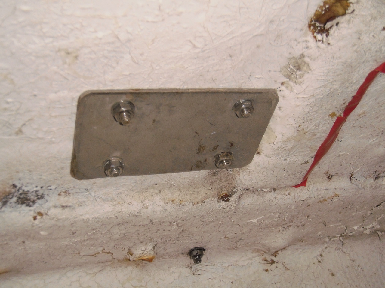


Starboard midships cleat backing plate

On Tuesday I spent some time at home in the workshop and silver soldered the modified engine sea water pipe ready to fit.


Sea water pipe completed

The sea water pipe was fitted on Wednesday it is now complete except for a coat of green Hammerite to match the rest of the engine.


Modified sea water pipe fitted to the engine

The next task was to finish glassing in the reinforcement to the galley moulding I used a couple of layers of 100mm woven glass fibre tape and epoxy resin such that the timber was completely encapsulated.


Galley moulding reinforcement

The top of the moulding is now much more rigid and a lot closer to being reasonably flat apart from a bit at the back under the lockers but to do anything with this area would entail grinding out the tabbing which secures the moulding to the half bulkhead and the hull and then levelling up the top and refixing it, but as the worktop is 12mm thick solid laminate which is pretty rigid and most of the top is pretty level particularly in way of the sink and taps I decided that it would be good enough.

Today I ran in the waste pipe which connects the heads washbasin waste, the discharge from the shower drain pump and the galley sink waste to the sea cock as shown in the above photograph the tee is for the connection to the galley sink waste it still requires some jubilee clips to complete but I have run out at the moment I also need the galley sink and a hose tail to connect the hose to the heads washbasin waste I shall get these on order this weekend.


Shower drain pump connection

To finish up today I removed the starboard chain plates so that I could reseal them while there was a minor leak on the port chain plates the starboard ones were OK however at the moment they are easy to get at but once the internal refit is completed the job will be a little more awkward and sods law usually says if I don't do them now once I get the boat sailing things are bound to work a bit and they will then start leaking. I cleaned everything up and washed with acetone before applying a generous dollop of Sikaflex and then lowered the plates in and bolted them back to the bulkheads and then fitted the deck plates and pulled them down until the Sikaflex was starting to be squeezed out once it has cured I will harden up the screws in the deck plates.


Chain plates ready to be replaced


Sikaflex being squeezed out round the deck plates


Friday, 7 April 2017

Engine

First job this week was to clean out the fuel tank it wasn't too bad but while it was still easy to remove I lifted it out of the locker and removed the inspection plate to enable me to give it a good wipe round inside. To finish up I washed the tank out with some industrial strength detergent and fortunately it was a warm sunny day so ti did not take long to dry out.

After some consideration I decided that as there was already a hole in the forward end of the tank about one inch from the bottom I would utilise this for the fuel supply to the engine by fitting a tank connector together with a ball type isolating valve and a hose tail. These tanks are normally arranged with a fuel outlet at the top of the tank with an internal pipe as this pipe extends to the very bottom of the tank I decided that I would use this as the water drain by connecting a vacuum pump, when required, of the type used for sucking out engine oil.


Fuel supply to engine

Over the weekend I had modified the return fuel connection by silver soldering a purpose made hose barb to the end of the copper pipe as I am not keen on connecting hose directly to plain copper pipe with jubilee clips, yes I know lots of people do it and don't have any problems. Also I could then use the same size fuel hose that I had used for the engine supply for the return to the tank. The right angled hose tail was then fitted to the tank inspection plate and the fuel return hose connected up.


Hose tail silver soldered to the fuel return 


Hose connected


Fuel return connected to tank

The hoses to connect the tank to the deck filling point and the fuel tank vent are still to be fitted once I have the required hose but it will still be possible to put fuel into the tank and the cap is fitted with a vent so that I will still be able to test run the engine. Also I have fitted a simple mechanical fuel gauge to the tank I will probably change this for a remote reading electric gauge in the future.

I have turned down the hose tail for the engine sea water pump to take a 1" hose but this has not been connected yet as I will use a temporary hose into a bucket for test running the engine.

When I fitted the new engine exhaust elbow I had to remove the copper sea water pipe which ran from the oil cooler to the cooling passage on the gearbox as there was not room for both as can be seen in the photograph below the sea water connection from the oil cooler is on the left just above the red teleflex throttle cable. I had been thinking of using a flexible hose but after some thought I found that I could probably modify the existing copper pipe one end of which was somewhat corroded although the rest of the pipe appeared to be sound .


The new exhaust connection


The corroded end of the sea water pipe

By cutting off the corroded end and the addition of a couple of copper elbows I found that I could divert the pipe around the exhaust connection the use of a capillary type fitting effectively forms a hose barb and will make the flexible hose connection to the oil cooler a much more secure fit, the original end of the pipe was finished in a similar fashion. The pipe required the attention of a file as it was of a slightly larger diameter than standard 28mm pipe. The modified pipe is in the workshop waiting to be soldered together it will have to wait until next week as I am going sailing this weekend Conyer round to Ramsgate and back on a friends boat.


Modified pipe awaiting soldering

The final connection to be made is the sea water hose from the engine heat exchanger  via an anti siphon device to the sea water injection point on the exhaust connection the connection on the exhaust requires 32mm hose while the connection on the heat exchanger is a bit less and on the first attempt the jubilee clip would not compress the hose sufficiently to give a tight fit I will investigate further next week.

Finally to finish up today I started the pipework for the shower drain pump this will drain via an up and over loop into the waste from the heads wash hand basin which will also connect to the galley sink waste.


Shower drain pump


Shower drain pump strum box.

The bilge under the shower still requires a good clean and a coat of paint


Friday, 31 March 2017

Success

This will be a fairly short post and in terms of actual work I do not have appeared to have done an awful lot this past week however what has been achieved has been very satisfying as it would appear for now anyway that there are no obvious major problems with the engine, I had already turned it by hand so I knew that it wasn't seized and there was some compression, I won't know for sure until I try and start the beast but the signs are looking positive and it was reported as running when the previous owner bought the boat some seven years ago so fingers crossed.

I spent some time on Monday investigating the engine wiring it had to be a fairly basic wiring problem as nothing worked not even the panel lights and after trying various ideas mostly around the negative connection it came to me the engine is wired with an isolated block and I had connected the negative battery connection to the engine block. The photograph that I had showed the negative from the panel connected to the negative terminal on the starter motor which was correct  but this photograph was taken after the engine had been removed from the boat so it wouldn't show the battery negative connection. After connecting the battery negative to the starter motor I tried the key and the starter motor turned the engine over, the pre-heater got hot and the panel became alive. I should have realised that the block was isolated as all the electrical bits on the engine, oil pressure transmitter, water temperature transmitter, pre-heater etc all have a positive and negative connection.

I had another go at linking the tablet to the chart plotter with no success, second to last resort was to try Google which came up with a Youtube video which explained the whole process the tablet refers to a password to make the connection while the plotter refers to a network key once the video explained the process for finding and changing the network key we were home and dry it all works the tablet now mirrors the plotter and can control the plotter and vice versa, the instruction manual would appear to be a bit lacking in this area. The last resort would have been to get no2 daughter to have a look. The plotter display does not show up too well in the photograph as it is set a lot brighter than the tablet.


Tablet connected to plotter

After that I went back to working on the wine locker I cut out a piece of teak to finish the timber rail which runs along under the deck I don't think that there was one fitted originally but I wanted to continue the concealed lighting theme along the starboard side.


New section of timber rail

I also replaced the ply shelf along the starboard side of the saloon I have yet to decide what I am going to do with this area whatever I decide to do the shelf would need to be in place and it gets it out of the way.


Shelf back in place

Now that I have a battery installed I have decided to move forward with getting the engine up and running basically all it requires the sea water and fuel systems to be completed he says hopefully so to this end I have installed the seawater strainer and some of the pipework and ordered the tank connections for the fuel return and the tank vent from Tek Tanks.


Sea water inlet pipe


Sea water strainer

This weekends homework project will be to turn down the hose connection for the engine seawater pump to take the one inch hose and to make and silver solder a hose connection to the fuel return pipe on the engine.


Friday, 24 March 2017

She lives and breathes again, well almost

The first job this morning was to stick in the laminate infill pieces over the internal doors I gave the epoxy a quick sanding down and a clean with acetone before attaching the laminate with contact adhesive the joint lines will be covered with a timber trim once the hardwood frames have been fitted.


Aft door


Forward door

The laminate does need a little bit of final trimming around the arch and also some infill pieces adjacent to the mast compression post on the aft door just to level things up a bit before the trim pieces are fitted.

The new service battery arrived yesterday so the main aim for today was to get it on board and connected so that I could get an idea of what was going to work and what would need further investigation. The battery was quite a heavy lump and as there was nobody around to give me a hand I had to tie a line round it and heave it up to deck level with one of the genoa sheet winches it was not so much of a problem getting it below as it was all downhill. I was quietly confident of the new wiring which I had installed from scratch so I started working through beginning with the saloon lighting there is still some work to be completed here but it is dependant on completion of the various lockers etc.


Saloon lighting white mode


Saloon lighting in night vision mode

The VHF radio was next I used a temporary aerial as the mast has not been put up I entered the  number and everything worked a treat the temporary aerial even picked up the French channel safety broadcast.


The VHF works

I tried the original Stowe echo sounder which seems to work OK but I guess it will have to wait until the boat is afloat before finding out for sure.

The switch panel is working fine including the battery voltmeter which I had my suspicions as when I fitted it to the panel at home I tried to test it on a battery charger and it didn't show anything I can only assume that it did not like the output of the battery charger which could well have been half wave rectification.


Switch panel

I temporarily plugged in the chart plotter which works fine I have a small problem in that I have a tablet, donated by my youngest daughter, which should connect to the plotter via the plotters own WiFi network the tablet recognises the WiFi but is asking for its network password which I don't seem to be able to find I shall have to investigate further. The plotter will be installed in the forward cockpit bulkhead so that it can be seen from the wheel and the tablet will be used as a repeater at the chart table and as the plotter needs a hole cutting in the infill panel on the bulkhead I shall leave the final installation until just before launching.


Plotter up and running

After a fairly productive day and with every confidence I inserted the key into the engine panel, with the intention of trying to turn it over, turned the key and nothing but a deathly silence not even a click of the starter relay I had a brief look but could not find an obvious reason I expect that somewhere there will be a connection which I have missed or made wrongly that will be a job for next week I don't have a wiring diagram for this engine the one in the manual that I downloaded from the interweb is for an older version all I had was the photographs the previous owner took when the engine came out I will just have to go through it all from scratch.

I started the week by installing the heads washbasin I took the worktop home last weekend and cut out the hole for it and so on Monday I stuck the worktop down with some polyurethane adhesive I used Puraflex 40 from Toolstation, other adhesives are available, its less than half the price of the more well known 'marine' grade stuff.  


Worktop glued into place

Once the adhesive had cured I dropped the basin into position and put a ring of masking tape round to prevent the adhesive that would be squeezed out, when the basin was pressed down, from making a mess over the worktop. I then roughened up the underside of the basin flange to provide a key for the adhesive and then ran a generous fillet around the basin.


Basin ready to fit

The basin was then pressed into place I stood my toolbox on it to hold it down until the adhesive had cured after which I cut round the edge of the basin with a sharp Stanley knife and removed the masking tape which left very little of the adhesive to clean up just a quick wipe with some acetone and it was done.


Before cleaning up


After removing the masking tape


After cleaning up

The basin looks a bit on the small side but I guess it will be sufficient for its intended purpose and being on the small side it will be a good water saving measure just got to source the mixer taps with shower hose I expect that I will have to pay chandlery prices for these as Aldi are unlikely to have them in their special offers.


Friday, 17 March 2017

Internal doors 3

This weeks post is a bit on the short side the main aim has been to progress the internal doorways after fitting the ply infill pieces last week. I have been cutting out and fitting the laminate to cover the infill pieces a straightforward job to cut the laminate to size and mark the curve of the top of the doorway then cut it out with the jig saw. The forward doorway laminate required some holes to clear the bolts for the baby stay chain plate I didn't want to clamp the laminate under the chain plate bolts as the tabbing which secures the bulkhead is a little uneven and I felt that it might crack the laminate if pulled up tight I will probably finish off with a varnished hardwood cover piece over these bolts.


Aft doorway


Forward doorway

Once I had finished the laminate pieces I glassed in the ply infill pieces on both sides to both doorways they were already secured with thickened epoxy and screws so this was just a bit of belt and braces. I shall leave the epoxy to cure for about a week before sticking the laminate down with contact adhesive.


Aft doorway infill pieces glassed in


Forward doorway infill pieces glassed in

Also this week I have varnished the shelves for various lockers and put them in place the interiors of these lockers still needs to be finished off either with paint or some of the carpet that I used for the headlining also the doors need making and fitting


Wine locker

Also this week I have sourced a small round stainless steel inset sink which I intend to use as the heads wash basin this was obtained from Screwfix the aim this weekend is to get the hole in the worktop cut out for it.


Friday, 10 March 2017

Internal doors 2

After cutting out the infill pieces for the forward doorway I temporarily screwed it in place to check the fit and when satisfied I mixed up some epoxy and primed the mating surfaces a coat of straight epoxy and then applied some epoxy thickened to a peanut butter consistency with colloidal silica and screwed both pieces in place.


Forward doorway infill pieces


Forward doorway infill trial fit


Forward doorway infill screwed and glued in place


Forward infill showing screws

Once the forward doorway had been dealt with I turned my attention to the aft doorway this was carried out in the same way as the forward doorway except as the bulkhead is thicker I used some off cuts of 18mm ply.


Aft door set up for marking the infill pieces

As for the forward doorway the aft infill pieces were cut out with the jig saw and then temporarily screwed into place to check the fit when I was satisfied with the fit I applied the epoxy and screwed them into place.


Aft doorway infill pieces in place

I have allowed for an 18mm thick frame for the curved top of the doorway these will probably be laminated the side frames will be made to suit the individual doorways they are both a different width as are the doors. The side frames will be made from solid timber planed to fit. I still have to glass in the infill pieces to make them as strong as possible and once this has been done I shall cut and glue in some laminate trim pieces to tidy up the doorways hopefully I should have sufficient left. 

The rest of the week was spent progressing the wine locker and the heads locker I have made the shelf for the heads locker and the bottle retainer for the wine locker the holes for the bottles will be cut out as my homework job for this weekend.


Heads locker shelf


Bottle retainer

I have also completed the joinery for securing the locker front panels and the shelves in both of these lockers the next step will be to paint and varnish the various parts.